Earthing Arrangements in Electrical Installations with Integrated Solar PV Systems: A Comprehensive Technical Guide
Introduction
Earthing is a fundamental aspect of electrical system design, ensuring both safety and operational stability. It helps maintain conductor voltages within safe insulation limits and enables protective devices to operate effectively during earth faults. For this reason, most medium- and high-voltage public supply systems are intentionally earthed, providing dependable fault-clearance paths and enhancing system security.
However, earthing cannot protect against faults that are not true earth faults. For instance, if a phase conductor on an overhead spur line breaks and only the remote end falls to the ground, the resulting current may be too small due to the high impedance of the connected load to operate earth-fault protection. In such cases, protective devices that rely on earth-fault current may not respond, other than current-balance protection at the substation. This underscores the importance of understanding the specific fault scenarios that earthing is designed to address.
According to IS 3043 (Code of Practice for Earthing), an electrical system is best considered as an integrated whole comprising the source of energy, the installation it supplies, and the supply cables connecting them. Designing earthing arrangements from this unified perspective ensures coordination between the supply system and the installation, enabling safe operation and effective fault management.
In a PV installation, the relationship between the supply (Grid) neutral and earth, the bonding of the module frames, the type of RCD used, and the value of the fault-loop impedance all directly influence how reliably the inverter and the protective devices operate. Therefore, when integrating PV into an installation, the earthing arrangement must be considered as part of a unified system comprising the energy source, the installation wiring, and the PV generating equipment.
The following technical article outlines how electrical systems are classified according to the various methods of system earthing for PV installations.
Key Definitions
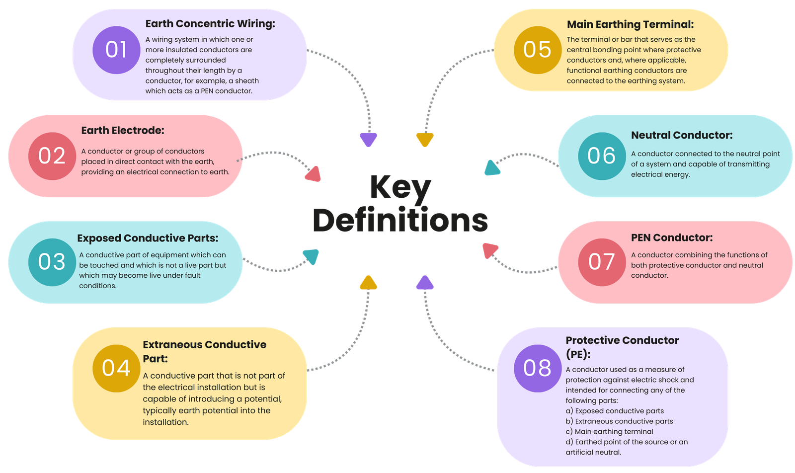
The following key terms, as defined in IS 3043, are essential for understanding the structure and operation of different earthing systems. These definitions provide the foundation for interpreting different configurations accurately.
Earthing Arrangements: Protective, Functional and Combined
1. Protective Earthing
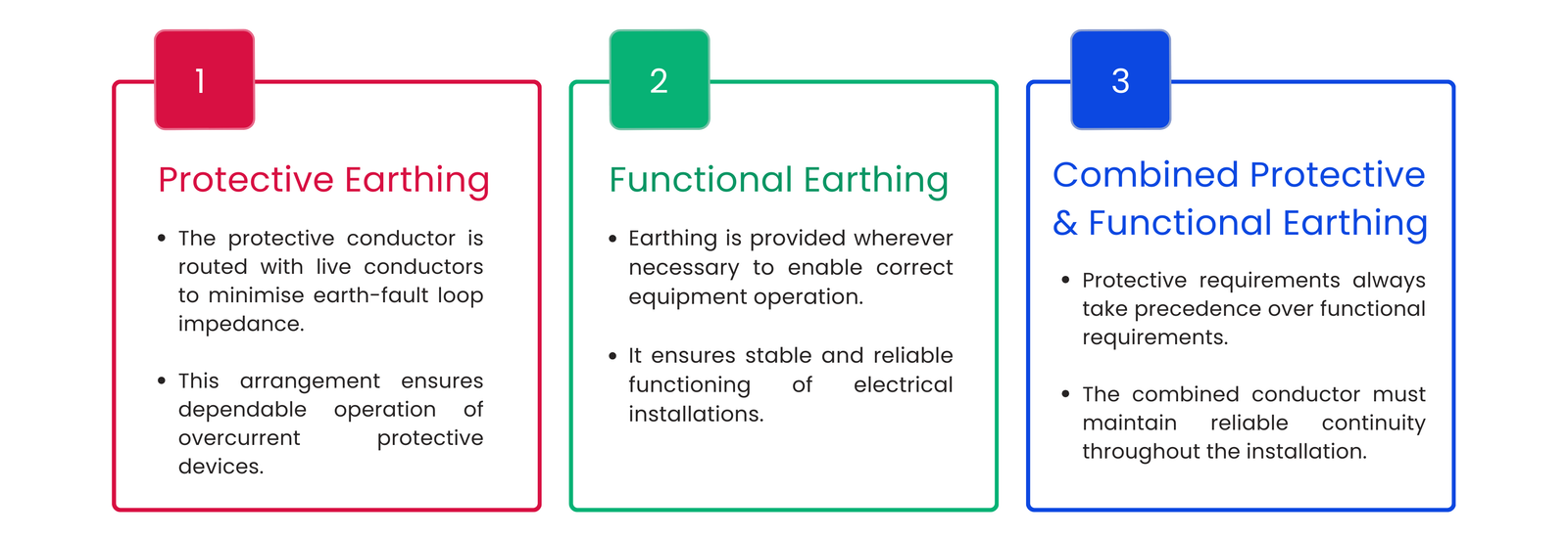
When overcurrent protective devices are used to provide protection against electric shock, it is strongly recommended that the protective conductor be routed within the same wiring system as the live conductors or positioned as close to them as practicable. This arrangement minimises the earth-fault loop impedance and supports the reliable operation of the protective device.
2. Functional Earthing
Earthing arrangements for functional purposes shall be provided wherever necessary to ensure the correct operation of equipment and to maintain the reliable and proper functioning of electrical installations
3. Combined Protective and Functional Earthing
Where earthing is required to serve both protective and functional purposes, the protective requirements always take priority. In TN systems, this often involves the use of a PEN conductor, which combines the neutral and protective functions within a single conductor. The PEN conductor must maintain reliable continuity throughout the installation and be insulated for the highest voltage it may encounter to minimise stray currents. Once the PEN conductor is separated into distinct protective conductor (PE) and neutral (N) conductor, these two conductors must not be reconnected downstream. At the separation point, independent terminals must be provided to ensure correct bonding, continuity, and safe operation of the installation.
Classification of Systems Based on Types of System Earthing
Internationally, earthing systems are classified into three main categories: TN, TT and IT, based on how the source is earthed and how exposed conductive parts are connected to earth. These classifications define the protective arrangements used in electrical installations.
For PV installations, these classifications determine how the PV module frames, inverter enclosure and neutral conductor must be connected, and they influence the requirements for RCD selection, surge protection, and anti-islanding performance.
1. TN system
In a TN system, one or more points of source of energy are directly earthed, and all exposed and extraneous conductive parts of the installation are connected to these earthed points through protective conductors. This arrangement provides a continuous metallic return path for earth-fault currents back to the source. TN systems are categorised into TN-S, TN-C and TN-C-S configurations based on how the neutral and protective conductors are arranged.
a) TN-S System
i) For 240 V single phase domestic/commercial supply
The system uses two separate conductors throughout the installation: one for the neutral (N) and another for the protective earth (PE).
Notes:
- The protective conductor (PE) is provided either by the metallic covering of the supply cable such as its armour or lead sheath or by a separate conductor.
- All exposed conductive parts of the installation are connected to this protective conductor through the installation’s main earthing terminal.
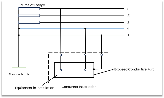
ii) For 415 V three-phase domestic commercial supply
A separate independent earth electrode is necessary within the consumer’s premises to provide a stable local earth reference.
Notes:
- 415 V three-phase domestic/commercial supply having 3 ~ and 1 ~ loads.
- All exposed conductive parts of the installation are connected to the protective conductor through the main earthing terminal of the installation, and an independent earth electrode within the consumer’s premises is necessary
PV Integration Requirements in TN-S System
- Neutral–Earth Bonding Restrictions:
A PV inverter must not create an additional N–PE bond, because the supply system already defines this bond at the source. Additional bonding can cause unintended DC leakage currents and false tripping. - Bonding of PV Frames:
All exposed conductive parts of the PV system (module frames, mounting structures, inverter enclosure) must be connected to the dedicated PE conductor, ensuring any fault triggers a clear earth-fault current path. - Low-Impedance Protection Path:
TN-S is inherently compatible with PV installations because the separated PE provides a dedicated, low-impedance path for automatic disconnection of supply, allowing MCBs, fuses and RCDs to meet disconnection times required by IEC standards.
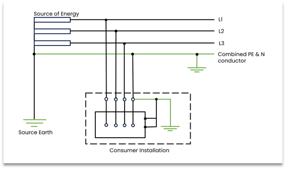
b) TN-C System
The neutral and protective functions are combined into a single conductor known as the PEN conductor throughout the installation, commonly implemented using earthed concentric wiring.
Notes:
- The protective conductor (PE) is provided either by the metallic covering of the supply cable such as its armour or lead sheath or by a separate conductor.
- All exposed conductive parts of the installation are connected to this protective conductor through the installation’s main earthing terminal.
PV Integration Restrictions in TN-C System
- PV equipment cannot be directly connected to a TN-C system because:
- The PEN conductor carries load current, creating potential touch-voltage hazards if it breaks.
- RCDs cannot function without a separate PE conductor, making TN-C unsuitable for PV’s residual-current protection needs.
- Before installing PV, conversion to TN-C-S is mandatory at the supply entry, where PEN is split into PE and N. PV equipment must only be connected after this separation.
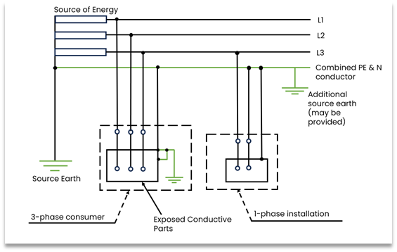
c) TN-C-S System
The neutral and protective functions are combined in a single conductor in part of the system, after which they are separated into distinct neutral (N) and protective conductor (PE) within the installation.
Notes:
- The usual form of a TN-C-S system is as shown, where the supply is TN-C and the arrangement in the installations in TN-S.
- This type of distribution is also known as Protective Multiple Earthing and the PEN conductor is referred to as the Combined Neutral and Earth (CNE)
- The supply system PEN conductor is earthed at several points and an earth electrode may be necessary at or near a consumer’s installation.
- All exposed conductive parts of an installation are connected to the PEN conductor via the main earthing terminal, and the neutral terminal, these terminals being linked together.
- Protective Neutral Bonding (PNB) is a type of TN-C-S system where the neutral and earth are connected together at only one point in the entire supply system.
PV Integration Requirements in TN-C-S System
- Correct PEN Separation Point:
The PEN split occurs at the main earthing terminal. PV inverters must connect only to the separated PE and N, not to the PEN. - Ensure No Re-bonding of PE and N:
There should be no additional PEN link downstream of the service entry, as it interferes with inverter monitoring and RCD operation. - Common Residential Application:
TN-C-S is widely used in domestic installations and generally compatible with PV, provided:- Correct RCD type is installed
- Protective conductor continuity is verified up to the PEN split point.
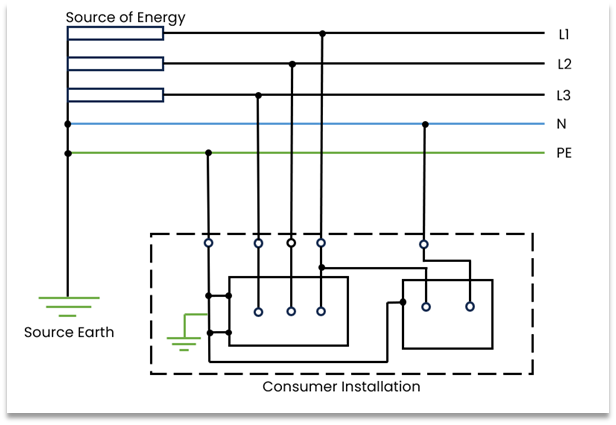
2. TT System
- The source has one or more points that are directly earthed.
- The exposed conductive parts of the installation are connected to a local earth electrode that is independent of the source earth.
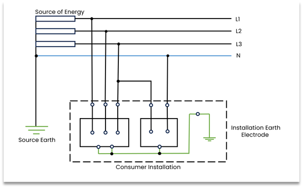
Notes:
- 415 V three-phase industrial supply having 3 ~ and 1 ~ loads.
- All exposed conductive parts are connected to an earth electrode independent of the supply earth.
PV Integration Requirements in TT System
- PV and Inverter Connection Requirements:
- All exposed conductive parts of the PV installation including module frames, mounting structures and the inverter enclosure must be bonded to the same local earth electrode through the main earthing terminal.
- The inverter must connect to the phase and neutral of the TT supply on the AC side, while its PE terminal must be connected exclusively to the local protective earth system, with no neutral–earth link allowed anywhere in the installation.
- Mandatory RCD Protection:
RCDs are the primary means of automatic disconnection of the supply because high earth impedance may prevent MCBs/fuses from tripping quickly. - Earth Electrode Resistance Requirements:
The local electrode must have sufficiently low resistance to ensure RCD disconnection times are met.
3. IT System
- The source is either not earthed or is earthed through a high-impedance connection.
- The installation’s exposed conductive parts are connected to independent local earth electrodes, separate from the source earthing.
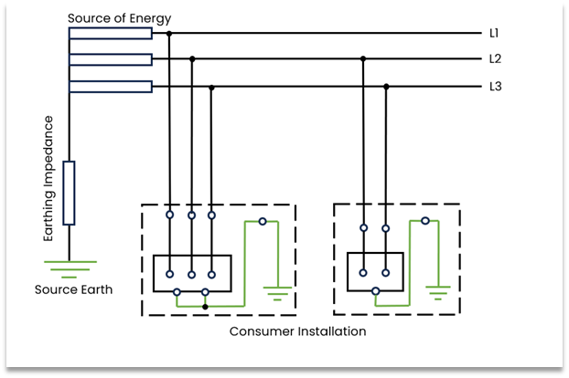
Notes:
- All exposed conductive parts of an installation are connected to an earth electrode.
- The source is either earthed through an intentionally added impedance or left completely isolated from earth.
PV Integration Requirements in IT System
- Inverter Compatibility:
Some grid-connected inverters require a solidly earthed neutral. Therefore, certain inverters cannot operate in IT systems without manufacturer approval. - Use of IMDs (Insulation Monitoring Devices):
IT systems do not disconnect on the first earth fault, so Insulation Monitoring Devices (IMDs) become mandatory to detect insulation deterioration. - Bonding of PV Frames:
Even in IT systems, PV module frames and inverter enclosures must be bonded to a local protective earth electrode, providing touch-voltage protection and improves SPD performance.
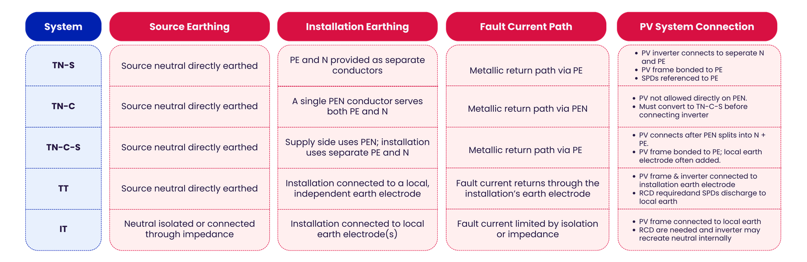
Comparison Table
Conclusion
As PV systems become an integral part of modern electrical installations, understanding how TN, TT, and IT earthing arrangements interact with solar inverters and PV arrays is essential for ensuring safety and reliable operation. Proper implementation of neutral–earth practices, careful bonding of conductive parts, correct RCD selection, and compliance with fault-loop impedance and surge protection requirements together form the foundation of a safe and resilient PV installation.
Great Article! Very nicely written!