Home » Blog » Infrared (IR) Thermography for Photovoltaic Systems

Infrared (IR) Thermography for Photovoltaic Systems

Introduction

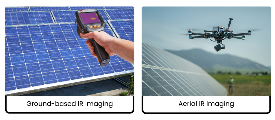
Infrared (IR) thermography has become one of the most valuable tools for inspecting photovoltaic (PV) systems because it allows defects to be detected while the plant is operating, without interrupting power generation. As PV installations grow from small rooftop systems to multi-hundred-megawatt utility plants, the need for reliable, non-intrusive inspection methods has increased significantly.

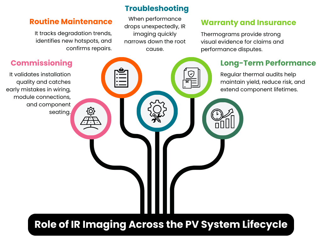
IR thermography reveals the thermal behaviour of PV modules and balance-of-system (BOS) components while the system is energized. Many PV defects first evident as localized heating long before power loss or physical damage becomes apparent. Therefore, IR inspections are widely used during commissioning, routine operation and maintenance (O&M), performance troubleshooting, and safety audits.

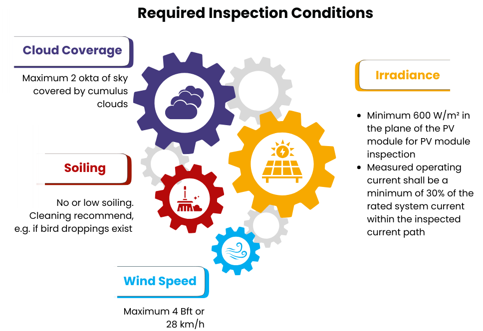
The technical standard “IEC TS 62446-Part 3: 2017 Outdoor infrared thermography” defines requirements for outdoor infrared thermographic inspections of photovoltaic (PV) modules and plants in operation. It covers equipment, environmental conditions, procedures, and reporting to identify thermal abnormalities, supporting preventive maintenance and performance optimization.

Figure 1: Role of IR Imaging Across the PV System Lifecycle

Principles of Infrared Thermography

All objects above absolute zero emit infrared radiation. The amount of radiation increases with temperature and depends on surface properties. An IR camera detects this radiation and converts it into a thermogram, where temperature differences are shown as colour variations.

In PV systems, temperature distribution is directly related to electrical performance. When current flows through cells and electrical components, small resistive losses generate heat. Under healthy operating conditions, temperature remains uniform across modules and components. However, defects disturb current flow and create localized heating.

Typical causes of abnormal heating include:

  • Cell microcracks or manufacturing defects
  • Damaged solder bonds or interconnects
  • Contact resistance in connectors or cables
  • Shading or soiling of modules
  • Bypass diode malfunction
  • Loose electrical connections

Detecting these anomalies early allows PV plant operators to address issues before performance loss or safety hazards arise.

Figure 2: Required Inspection Conditions for IR thermography

Inspection Levels

Thermographic inspections can be broadly classified into two levels.

  1. Simplified Thermography
  2. Detailed Thermography

Simplified thermography is used mainly for commissioning or quick checks, simplified inspections focus on identifying obvious abnormal thermal patterns without detailed temperature measurements. It helps confirm whether modules and strings appear to operate normally but does not provide precise fault classification.

Detailed thermography is used perform quantitative temperature analysis. Measurements are taken at specific points and across areas, and comparisons are made between normal and abnormal regions. This is required for performance troubleshooting and long-term asset management.

This approach helps:

  • Quantify fault severity
  • Identify root causes
  • Plan corrective actions
  • Monitor degradation trends

Figure 3: Difference between Simplified Thermography and Detailed Thermography

Ground-Based vs Aerial IR Thermography

IR inspections can be performed from the ground using handheld cameras or from the air with drones. Each method has unique strengths that suit different scenarios.

Ground-Based IR Imaging

Operators use handheld cameras while walking along module rows. This approach offers:

  • High-resolution close-up analysis
  • Inspection of connectors, junction boxes, and combiner panels
  • Immediate visual confirmation of issues

A key benefit is the ability to align thermal findings with visual inspection. For example, a hotspot caused by bird droppings can be confirmed immediately.

Aerial IR Imaging

Drones equipped with thermal cameras can scan very large plants rapidly. Benefits include:

  • Coverage of large areas in short time
  • Access to difficult terrain
  • Automated mapping and anomaly detection
  • Repeatable inspections over time

However, aerial surveys usually provide broader fault identification, and anomalies often need ground verification. Many plants therefore use a hybrid approach using drone thermography for large-area screening followed by targeted ground inspections for root-cause analysis.

Figure 4: Difference between Ground based and Aerial Imaging

Thermal Patterns – What They Reveal

The thermal patterns observed on PV modules indicate underlying electrical, material, or environmental issues. The table below summarizes common module-level thermal anomalies, their typical appearance, likely causes, and technical interpretation.

Table 1: Thermal Patterns, Typical Appearance and Likely Defects

IR thermography also reveals abnormal heating in balance-of-system (BOS) components, often associated with increased resistance, installation issues, or component degradation. The table below outlines common BOS thermal patterns and their technical interpretation.

Table 2: Components, Typical Appearance and Likely Defects

Figure 5: IR images of Modules, Inverters and Wires

Conclusion

Infrared thermography is one of the most powerful non-contact diagnostic tools available for PV systems. It enables early detection of electrical and structural problems, improves safety, and helps maintain plant performance without disrupting operations. When applied correctly and interpreted by qualified professionals, IR imaging becomes an indispensable tool throughout the entire lifecycle of modern photovoltaic systems.

Inspection reliability strongly depends on inspector competence. International standards recommend trained and certified thermographers, especially for detailed inspections. Personnel should be trained to understand both PV system operation and thermographic interpretation.

Leave a Reply

Your email address will not be published. Required fields are marked *